FREE
circuits!
How to build 48V Phantom (Microphone) Power Supply
September 30, 2010 - category: DC power supplyDescription
48 V ‘phantom’ powering has become the standard for professional condenser microphones. The supply (or rather bias) voltage is applied over both wires of the balanced screened cable via two 6k8 resistors (see reference [1]) – the absolute value is not critical, since a variation of ±20% is permitted, but they must be matched to an accuracy of 0.4% or better [2]. Many microphones are fitted with an output transformer, and derive their power from a center-tap on the secondary.
If the currents supplied by the two wires of the balanced line, which flow in opposite directions through the two halves of the secondary winding, are not identical, the magnetic fluxes they induce in the core of the transformer do not cancel out properly, and spurious magnetization occurs, causing distortion and a reduction in the microphone’s dynamic range. With an output current of 0.4 A, the PSU described in this article can ‘supply’ at least 40 microphones. The mains voltage is applied to a 30 VA transformer which supplies 24 Vrms.
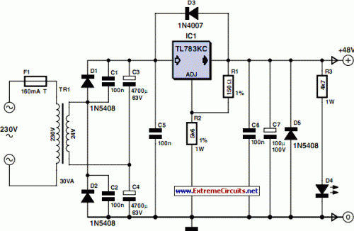
Circuit diagram
Its secondary feeds a voltage doubling rectifier formed by diodes D1 and D2 and capacitors C3 and C4. Capacitors C1 and C2 suppress the switching noise produced by the rectifier diodes. This voltage-doubling rectifier provides around 72 V DC, and so offers an adequate margin to allow for ±10% fluctuations in the mains voltage.
Voltage regulation is taken care of by TL783KC regulator IC1 on which an abundant amount of information may be found at [3]. Basically, this is an adjustable regulator in a TO220 package that offers excellent residual ripple and low noise on its output voltage. The TL783KC regulator includes a MOS series pass transistor and accepts an input voltage of up to 125 V, making it an ideal candidate for this application. Diodes D3 and D5 respectively protect the PSU against transients at switch-off and reversed polarity. The output voltage is set by resistors R1 and R2 according to the formula:
Vout = Vref × (1 + R2 / R1)
where reference voltage Vref = 1.27 V. These resistors should preferably have a tolerance of 1%, and R2 is likely to dissipate 0.5 W. Resistor R3 provides a minimum load that is vital for maintaining the PSU’s off-load voltage at 48 V, and is also used to supply LED D4. If the LED is not used, R3 must without fail be connected to ground. Last but not least, regulator IC1 must be mounted on a heatsink with a thermal resistance of less than 1.5 °C/W using the standard insulating kit: top-hat insulating washer, mica washer, and heat sink compound... make sure you use enough, but not too much!
author: Joseph Kreutz, Elektor Electronics 2008
circuit from http://www.extremecircuits.net/2010/05/48v-phantom-microphone-power-supply.html


 This category