FREE
circuits!
Current and voltage circuit diagrams
- 1
- 2
December 28, 2010
A milliamp meter can be used as a volt meter by adding a series resistance. The resistance needed is the full scale voltage reading divided by the full scale current of the meter movement. So,... [more]
December 25, 2010
The ICL7107 is a 3 1/2 digit LED A/D convertor. It contains an internal voltage reference, high isolation analog switches, sequential control logic, and the display drivers. [more]
December 12, 2010
Measures 10mV to 50Volt RMS in eight ranges Simply connect to your Avo-meter set @ 50uA range [more]
December 8, 2010
This circuit uses a CA3420 BiMOS op amp to form a picoammeter with 4 ranges. The exceptionally low input current (typically 0.2pA) makes the CA3420 highly suited for use in a picoammeter circuit. Input transient... [more]
November 30, 2010
This circuit is a Logic Probe. It indicates the logic state of the node of any TTL logic circuit. To do that, we have to supply the probe with the same power of the circuit... [more]
November 30, 2010
This circuit runs a fast battery test without the need of power supply or expensive moving-coil voltmeters. It has two ranges: when SW1 is set as shown in the circuit diagram, the device can test... [more]
November 16, 2010
This low voltage circuit can be used to monitor batteries and other volatile sources of current for problems. The circuit sounds an alarm and lights an LED, but can be interfaced to any number of... [more]
September 27, 2010
This circuit is not a novelty, but it proved so useful, simple and cheap that it is worth building. When the positive (Red) probe is connected to a DC positive voltage and the Black probe... [more]
circuit from:http://www.extremecircuits.net/2009/08/dc-or-ac-voltage-indicator-circuit.html
September 27, 2010
If the unit is brought close to a live conductor (insulated, and even buried in plaster) capacitive coupling between the live conductor and the probe clocks the counter, and causes the LED to flash 5... [more]
circuit from:http://www.extremecircuits.net/2009/12/live-line-detector-indicator-circuit.html
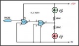
September 26, 2010
This simple logic probe has both LEDs on with no signal at the input but due to the nor gates connected to the probe, indicates correctly when a high or low signal is present. It... [more]
circuit from:http://www.extremecircuits.net/2010/05/simple-logic-probe.html
- 1
- 2
 This category