FREE
circuits!
Recently added diagrams and projects
October 5, 2010
This circuit uses an LM11 to form a voltage follower with 1G ohm input resistance built using standard resistor values. With the input disconnected, the input offset voltage is multiplied by the same factor as... [more]
October 5, 2010
When the input voltage is 0 the LED glows. The LED stops glowing when the voltage rises to the level determined by R2. Reverse + and - pins to reverse operating mode. To set voltage... [more]
October 5, 2010
Some 15 years ago it was common to see small key-holders emitting an intermittent beep for a couple of seconds after its owner whistled. These devices contained a special purpose IC and therefore were not... [more]
October 5, 2010
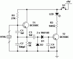
This is a simple XTal tester circuit. T1 and XTal have formed an oscillator. C1 and C2 are voltage divider for oscillator. if the XTal is safe, the oscillator will work well and its output... [more]
October 5, 2010
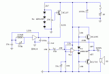
Designed around the popular ZN414 ic this receiver covers the AM band from 550 - 1600 KHz with the values shown. For Longwave the coil needs to be changed. Use one from an old MW... [more]
October 4, 2010
This circuit is similar to the LED clock using 12 neon indicator lamps instead of LEDs. It operates from 2 high capacity ni-cad cells (2.5 volts) which keep it going for a couple weeks. High... [more]
October 4, 2010
This is basically a Schmitt Trigger circuit which receives input from a cadmium sulfide photo cell and controls a relay that can be used to switch off and on a street lamp at dawn and... [more]
October 4, 2010
Here is a simple thermostat circuit that can be used to control a relay and supply power to a small space heater through the relay contacts. The relay contacts should be rated above the current... [more]
October 4, 2010
This circuit will detect AC line currents of about 250 mA or more without making any electrical connections to the line. Current is detected by passing one of the AC lines through an inductive pickup... [more]


 All posts